Spencer's Method
Spencer's Method is a complete equilibrium slope stability method that satisfies both force and moment equilibrium and can be used on circular and non-circular slip surfaces. The primary assumption for Spencer's method is that all side forces are parallel, i.e., the interslice forces have a constant inclination angle \(\theta\). Because it satisfies all conditions of equilibrium, Spencer's method is the most rigorous procedure in xslope and is the recommended choice for design; the other methods are best treated as comparative checks against it.
The following derivation is adapted from the US Army Corps of Engineers (USACE) UTEXAS Version 2.0 user manual, which is based on the original work by Spencer (1967). The UTEXAS manual can be accessed via this link. The equations come from Appendix A which was authored by Stephen G. Wright at the University of Texas at Austin, and the primary author of the UTEXAS slope stability software.
Slice Geometry and Forces
The geometry and the forces associated with a representative slice on a left-facing slope are as follows:
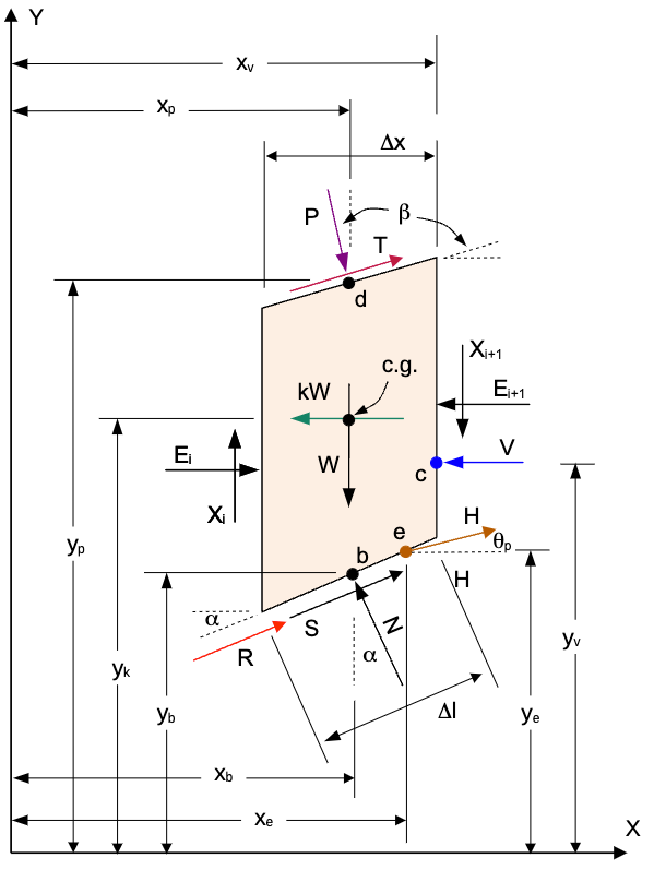
where:
\(W\) = weight of the slice
\(N\) = normal force on the base of the slice
\(S\) = shear force on the base of the slice
\(E_i\) = horizontal interslice force on the left side of the slice
\(X_i\) = vertical interslice force on the left side of the slice
\(E_{i+1}\) = horizontal interslice force on the right side of the slice
\(X_{i+1}\) = vertical interslice force on the right side of the slice
\(kW\) = seismic force on the center of gravity (c.g.) of the slice
\(P\) = normal force on the top of the slice
\(d\) = point of action for the normal force on the top of the slice
\(T\) = shear force on the top of the slice
\(R\) = reinforcement force at point \(r = (x_r, y_r)\) on the base of the slice, at angle \(\psi\) from horizontal
\(\psi\) = reinforcement force angle: \(\psi = \alpha\) for tangent/flexible reinforcement (the default), or the line's own inclination for axial/rigid reinforcement
\(V\) = resultant force of water in tension crack (only applies to last slice)
\(c\) = point of action for the resultant force of water in the tension crack
\(H\) = pile/pier force at point \(e\) on the failure surface
\(\theta_p\) = angle of pile force from horizontal (positive = counterclockwise/upward)
\(L\) = line load at point \(f = (x_f, y_f)\) on the top of the slice
\(\delta\) = angle of the line load from horizontal (default \(-90°\) = straight down)
\(\beta\) = angle of the top of the slope
\(\alpha\) = angle of the base of the slice
\(\Delta \ell\) = length of the base of the slice
\(\Delta x\) = width of the slice
Passive support in the Newton system
Passive support forces mobilize with the soil and carry a factor \(1/F\), which makes the force sums \(F\)-dependent: \(F_h(F) = F_h + F_{h,p}/F\), \(F_v(F) = F_v + F_{v,p}/F\), and \(M_o(F) = M_o + M_{o,p}/F\), where the \(p\)-subscripted terms collect the passive components. The constants in the \(Q\) expression then become \(C_1(F) = C_{1,0} + C_{1,p}/F\) and \(C_2(F) = C_{2,0} + C_{2,p}/F\) with \(C_{1,p} = -F_{v,p}\sin\alpha - F_{h,p}\cos\alpha\) and \(C_{2,p} = (F_{v,p}\cos\alpha - F_{h,p}\sin\alpha)\tan\phi\), and the Newton derivatives generalize to
with \(N = C_1 + C_2/F\) and \(D = C_3 + C_4/F\), plus a \(-M_{o,p}/F^2\) term in \(\partial y_Q/\partial F\). With no passive elements (\(C_{1,p} = C_{2,p} = M_{o,p} = 0\)) every expression reduces exactly to the classical closed forms below.
Note: In the current implementation of Spencer's method in xslope, the shear force, \(T\), at the top of the slice is not simulated. It is included here for completeness in case it is added in the future. The reinforcement force \(R\) acts at the point \(r\) where the line crosses the base, at angle \(\psi\): for Dir = Tangent (flexible, the default) \(\psi = \alpha\) and \(r\) is taken at the base center \((x_b, y_b)\); for Dir = Axial (rigid) \(\psi\) is the line's own inclination and \(r\) is the actual crossing point. When Appl = Active (default) \(R\) is not divided by \(F\); when Passive it is. All of the other forces are included.
This page follows the UTEXAS symbol convention, in which \(P\) is the distributed-load resultant on the top of the slice and \(R\) is the reinforcement force. On the OMS, Bishop, Janbu, and force-equilibrium pages these same two forces are written \(D\) (distributed load) and \(P\) (reinforcement), respectively.
General Equations
The equations for Spencer's method are derived from the equilibrium of forces and moments acting on the slice. One of the key features of Spencer's method is how the side forces are represented and lumped to a single force \(Q_i\), which will be introduced later. Thus, it is helpful to sum forces and moments using the forces acting on the slice except for the side forces and \(N\) and \(S\). Summing forces in the horizontal and vertical directions gives:
\(F_h = -kW - V + P \sin \beta + T \cos \beta + R \cos \psi + H \cos \theta_p + L \cos \delta \qquad (1)\)
\(F_v = - W - P \cos \beta + T \sin \beta + R \sin \psi + H \sin \theta_p + L \sin \delta \qquad (2)\)
Likewise, summing moments about the center of the base of the slice gives:
\(\begin{aligned} M_o &= - P \sin \beta (y_p - y_b) - P \cos \beta (x_p - x_b) - T \cos \beta (y_p - y_b) \\ &\quad + T \sin \beta (x_p - x_b) + kW (y_k - y_b) + V (y_v - y_b) \\ &\quad - H \cos \theta_p (y_e - y_b) + H \sin \theta_p (x_e - x_b) \\ &\quad - R \cos \psi (y_r - y_b) + R \sin \psi (x_r - x_b) \\ &\quad - L \cos \delta (y_f - y_b) + L \sin \delta (x_f - x_b) \end{aligned} \qquad (3)\)
Note that counter-clockwise moments are positive (right-hand rule).
For tangent reinforcement the moment terms involving \(R\) vanish because the force acts at the base center \((x_b, y_b)\), making its moment arms zero. For axial reinforcement, \(r\) is the actual crossing point on the base, so the arms \((y_r - y_b)\) and \((x_f - x_b)\) are small but nonzero; the direction effect is carried primarily through the force components in (1)-(2) and the interslice force propagation. The line load acts at point \(f\) on the top of the slice, so its moment arms are generally significant.
The shear force on the base of the slice is:
\(S = \tau \Delta \ell \qquad (4)\)
where \(\tau\) is the shear stress on the base of the slice. Recall that from limit equilibrium, the factor of safety \(F_s\) is defined as the ratio of the resisting shear strength \(s\) to the driving stress \(\tau\):
\(F_s = \dfrac{s}{t} \qquad (5)\)
The shear strength \(s\) is given by:
\(s = c' + (\sigma - u) \tan \phi' \qquad (6)\)
This can also be written in terms of effective stress as:
\(s = c' + \sigma' \tan \phi'\)
where\(\sigma'\) = \(\sigma - u\). It is also convenient to express the shear stress in terms of the mobilized shear strength as follows:
\(\tau = \dfrac{c' + (\sigma - u) \tan \phi'}{F} \qquad (7)\)
Combining equations (4) and (7) gives:
\(S = \dfrac{c' \Delta \ell + (N - u \Delta \ell) \tan \phi'}{F} \qquad (8)\)
Sometimes this is written as:
\(S = \dfrac{c' \Delta x \sec \alpha + (N - u \Delta x \sec \alpha) \tan \phi'}{F} \qquad (9)\)
where \(\Delta x \sec \alpha\) = \(\Delta \ell\).
Using total stresses, the shear stress can be expressed as:
\(s = c + \sigma \tan \phi \qquad (10)\)
And in terms of forces:
\(S = \dfrac{c \Delta \ell + N \tan \phi}{F} \qquad (11)\)
or:
\(S = \dfrac{c \Delta x \sec \alpha + N \tan \phi}{F} \qquad (12)\)
where \(c\) is the total cohesion, and \(\phi\) is the total angle of internal friction.
Spencer's Method Equations
As stated above, The primary assumption for Spencer's method is that all side forces are parallel, i.e., the interslice forces have a constant inclination angle \(\theta\). Thus, there are two unknowns: the inclination angle \(\theta\) and the factor of safety \(F\). The interslice forces are lumped to a single force \(Q\) as follows:
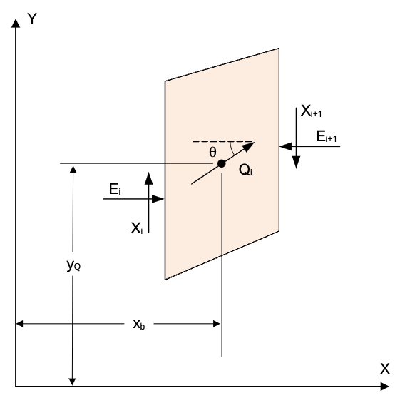
Since \(Q\) is the resultant of the interslice forces and acts through a single point, the resultant of all of the other forces must be equivalent to \(Q\). Thus, for overall equilibrium, we can work in terms of \(Q\). Summing over all slices, we have:
\(\sum Q \cos \theta = 0 \qquad (13)\)
\(\sum Q \sin \theta = 0 \qquad (14)\)
Since \(\theta\) is constant, we can simplify these equations to:
\(\sum Q = 0 \qquad (15)\)
For the moment equilibrium, we can sum moments about the origin as follows:
\(\sum Q (x_b \sin \theta - y_Q \cos \theta) = 0 \qquad (16)\)
Solving for Q
Next, we need to solve for \(Q\). To do this, we can use equations (1-3) derived above for the forces and moments. First, we will sum forces perpendicular to the base of the slice. This gives:
\(N + F_v \cos \alpha - F_h \sin \alpha - Q \sin (\alpha - \theta) = 0 \qquad (17)\)
Solving for the normal force \(N\) gives:
\(N = - F_v \cos \alpha + F_h \sin \alpha + Q \sin (\alpha - \theta) \qquad (18)\)
Substituting this into equation (9) gives:
\(S = \dfrac{1}{F} \left[ c' \Delta x \sec \alpha + (- F_v \cos \alpha + F_h \sin \alpha + Q \sin (\alpha - \theta) - u \Delta x \sec \alpha) \tan \phi' \right] \qquad (19)\)
Next, we can sum forces parallel to the base of the slice. This gives:
\(S + F_v \sin \alpha + F_h \cos \alpha + Q \cos (\alpha - \theta) = 0 \qquad (20)\)
Solving for \(S\) gives:
\(S = - F_v \sin \alpha - F_h \cos \alpha - Q \cos (\alpha - \theta) \qquad (21)\)
Combining equations (19) and (21) gives:
\(\dfrac{1}{F} \left[ c' \Delta x \sec \alpha + (- F_v \cos \alpha + F_h \sin \alpha + Q \sin (\alpha - \theta) - u \Delta x \sec \alpha) \tan \phi' \right] = - F_v \sin \alpha - F_h \cos \alpha - Q \cos (\alpha - \theta) \qquad (22)\)
Solving for \(Q\) gives:
\(Q = \left[ - F_v \sin \alpha - F_h \cos \alpha - \dfrac{c'}{F} \Delta x \sec \alpha + (F_v \cos \alpha - F_h \sin \alpha + u \Delta x \sec \alpha) \dfrac{\tan \phi'}{F} \right] m_{\alpha} \qquad (23)\)
where:
\(m_{\alpha} = \dfrac{1}{\cos (\alpha - \theta) + \sin (\alpha - \theta) \dfrac{\tan \phi'}{F}} \qquad (24)\)
Next, we need to solve for \(y_Q\). To do this, we sum moments about the center of the base of the slice. The moment from \(Q\) must equal the moment from the other forces \(M_o\) from equation (3). Therefore:
\(- Q \cos \theta (y_Q - y_b) + M_o = 0 \qquad (25)\)
Solving for \(y_Q\) gives:
\(y_Q = y_b + \dfrac{M_o}{Q \cos \theta} \qquad (26)\)
Solution of Equilibrium Equations
The expressions for \(Q\) (from the force derivation) and \(y_Q\) (the line of action coordinate) are substituted into the equations of equilibrium to produce two equations in two unknowns (\(F\) and \(θ\)) which must be satisfied to satisfy static equilibrium. The solution for the factor of safety and side-force inclination is accomplished using an iterative procedure based on Newton's method for solving two equations in two unknowns.
For assumed values of the factor of safety \(F_0\) and side-force inclination \(\theta_0\), it is convenient to write the two equilibrium equations in the form:
\(R_1 = \sum Q_0 \quad(27)\)
\(R_2 = \sum Q_0(x_b \sin \theta_0 - y_{Q_0} \cos \theta_0) \qquad (28)\)
where:
\(Q_0\) = value of \(Q\) based on the assumed values \(F_0\) and \(\theta_0\)
\(R_1, R_2\) = force and moment imbalances, respectively, based on the assumed values \(F_0\) and \(\theta_0\)
Application of Newton's method to find the roots corresponding to \(R_1 = R_2 = 0\) gives the following for the new estimates:
\(F_1 = F_0 + \Delta F \qquad (29)\)
\(\theta_1 = \theta_0 + \Delta \theta \qquad (30)\)
where \(\Delta F\) and \(\Delta \theta\) represent adjustments to the assumed values to be used for the next iteration.
Basic Newton Method
The expressions for \(\Delta F\) and \(\Delta \theta\) are:
\(\Delta F = \dfrac{R_1 \dfrac{\partial R_2}{\partial \theta} - R_2 \dfrac{\partial R_1}{\partial \theta}}{\dfrac{\partial R_1}{\partial \theta} \dfrac{\partial R_2}{\partial F} - \dfrac{\partial R_1}{\partial F} \dfrac{\partial R_2}{\partial \theta}} \qquad (31)\)
\(\Delta \theta = \dfrac{R_2 \dfrac{\partial R_1}{\partial F} - R_1 \dfrac{\partial R_2}{\partial F}}{\dfrac{\partial R_1}{\partial \theta} \dfrac{\partial R_2}{\partial F} - \dfrac{\partial R_1}{\partial F} \dfrac{\partial R_2}{\partial \theta}} \qquad (32)\)
Extended Newton Method
Equations (31) and (32) are applied iteratively until the values become less than certain limits (\(\Delta F = 0.5, \Delta \theta = 0.15\) radians). At that point, an "extended" form of Newton's method is used based on Taylor series expansions including second-order terms:
\(R_1 + \Delta F \dfrac{\partial R_1}{\partial F} + \Delta \theta \dfrac{\partial R_1}{\partial \theta} + \dfrac{1}{2} \Delta F^2 \dfrac{\partial^2 R_1}{\partial F^2} + \Delta F \Delta \theta \dfrac{\partial^2 R_1}{\partial F \partial \theta} + \dfrac{1}{2} \Delta \theta^2 \dfrac{\partial^2 R_1}{\partial \theta^2} = 0 \qquad (33)\)
\(R_2 + \Delta F \dfrac{\partial R_2}{\partial F} + \Delta \theta \dfrac{\partial R_2}{\partial \theta} + \dfrac{1}{2} \Delta F^2 \dfrac{\partial^2 R_2}{\partial F^2} + \Delta F \Delta \theta \dfrac{\partial^2 R_2}{\partial F \partial \theta} + \dfrac{1}{2} \Delta \theta^2 \dfrac{\partial^2 R_2}{\partial \theta^2} = 0 \qquad (34)\)
Estimates of new trial values are obtained by solving these two equations simultaneously for \(\Delta F\) and \(\Delta \theta\).
Required Partial Derivatives
First-Order Partial Derivatives of R₁
\(\dfrac{\partial R_1}{\partial F} = \sum \dfrac{\partial Q}{\partial F} \qquad (35)\)
\(\dfrac{\partial R_1}{\partial \theta} = \sum \dfrac{\partial Q}{\partial \theta} \qquad (36)\)
Second-Order Partial Derivatives of R₁
\(\dfrac{\partial^2 R_1}{\partial F^2} = \sum \dfrac{\partial^2 Q}{\partial F^2} \qquad (37)\)
\(\dfrac{\partial^2 R_1}{\partial F \partial \theta} = \sum \dfrac{\partial^2 Q}{\partial F \partial \theta} \qquad (38)\)
\(\dfrac{\partial^2 R_1}{\partial \theta^2} = \sum \dfrac{\partial^2 Q}{\partial \theta^2} \qquad (39)\)
First-Order Partial Derivatives of R₂
\(\dfrac{\partial R_2}{\partial F} = \sum \dfrac{\partial Q}{\partial F} \left( x_b \sin \theta_0 - y_{Q_0} \cos \theta_0 \right) - \sum Q_0 \left(\dfrac{\partial y_Q}{\partial F} \cos \theta_0 \right) \qquad (40)\)
\(\dfrac{\partial R_2}{\partial \theta} = \sum \dfrac{\partial Q}{\partial \theta}(x_b \sin \theta_0 - y_{Q_0} \cos \theta_0) + \sum Q_0 \left( x_b \cos \theta_0 + y_{Q_0} \sin \theta_0 - \dfrac{\partial y_Q}{\partial \theta} \cos \theta_0 \right) \qquad (41)\)
Second-Order Partial Derivatives of R₂
\(\dfrac{\partial^2 R_2}{\partial F^2} = \sum \dfrac{\partial^2 Q}{\partial F^2}(x_b \sin \theta_0 - y_{Q_0} \cos \theta_0) - 2\sum \dfrac{\partial Q}{\partial F} \left( \dfrac{\partial y_Q}{\partial F} \cos \theta_0 \right) - \sum Q_0 \left( \dfrac{\partial^2 y_Q}{\partial F^2} \cos \theta_0 \right) \qquad (42)\)
\(\dfrac{\partial^2 R_2}{\partial F \partial \theta} = \sum \dfrac{\partial^2 Q}{\partial F \partial \theta}(x_b \sin \theta_0 - y_{Q_0} \cos \theta_0) + \sum \dfrac{\partial Q}{\partial F} \left(x_b \cos \theta_0 + y_{Q_0} \sin \theta_0 - \dfrac{\partial y_Q}{\partial \theta} \cos \theta_0 \right) - \sum \dfrac{\partial Q}{\partial \theta} \left( \dfrac{\partial y_Q}{\partial F} \cos \theta_0 \right) - \sum Q_0 \left( \dfrac{\partial^2 y_Q}{\partial F \partial \theta} \cos \theta_0 - \dfrac{\partial y_Q}{\partial F} \sin \theta_0 \right) \qquad (43)\)
\(\dfrac{\partial^2 R_2}{\partial \theta^2} = \sum \dfrac{\partial^2 Q}{\partial \theta^2}\left(x_b \sin \theta_0 - y_{Q_0} \cos \theta_0\right) + 2\sum \dfrac{\partial Q}{\partial \theta}\left(x_b \cos \theta_0 + y_{Q_0} \sin \theta_0 - \dfrac{\partial y_Q}{\partial \theta} \cos \theta_0\right) - \sum Q\left(x_b \sin \theta_0 - y_{Q_0} \cos \theta_0 - 2 \dfrac{\partial y_Q}{\partial \theta} \sin \theta_0 + \dfrac{\partial^2 y_Q}{\partial \theta^2} \cos \theta\right) \qquad (44)\)
Partial Derivative Equations
In evaluating the various partial derivatives, it is convenient to write the expression for Q as:
\(Q = \dfrac{C_1 + \dfrac{C_2}{F}}{C_3 + \dfrac{C_4}{F}} \qquad (45)\)
where:
\(C_1 = -F_v \sin \alpha - F_h \cos \alpha \qquad (46)\)
\(C_2 = -c \Delta x \sec \alpha + (F_v \cos \alpha - F_h \sin \alpha + u \Delta x \sec \alpha) \tan \phi \qquad (47)\)
\(C_3 = \cos(\alpha - \theta) \qquad (48)\)
\(C_4 = \sin(\alpha - \theta) \tan \phi \qquad (49)\)
First-Order Partial Derivatives of Q
\(\dfrac{\partial Q}{\partial F} = \dfrac{-1}{\left(C_3 + \dfrac{C_4}{F}\right)^2} \left[\left(C_3 + \dfrac{C_4}{F}\right) \dfrac{C_2}{F^2} - \left(C_1 + \dfrac{C_2}{F}\right) \dfrac{C_4}{F^2}\right] \qquad (50)\)
\(\dfrac{\partial Q}{\partial \theta} = \dfrac{-1}{\left(C_3 + \dfrac{C_4}{F}\right)^2} \left(C_1 + \dfrac{C_2}{F}\right) \left(\dfrac{\partial C_3}{\partial \theta} + \dfrac{1}{F} \dfrac{\partial C_4}{\partial \theta}\right) \qquad (51)\)
Second-Order Partial Derivatives of Q
\(\dfrac{\partial^2 Q}{\partial F^2} = \dfrac{1}{\left(C_3 + \dfrac{C_4}{F}\right)^3} \left \{ \left(C_3 + \dfrac{C_4}{F}\right) \left[2\left(C_3 + \dfrac{C_4}{F}\right) \dfrac{C_2}{F^3} - 2\left(C_1 + \dfrac{C_2}{F}\right) \dfrac{C_4}{F^3}\right] - 2 \dfrac{C_4}{F^2} \left[\left(C_3 + \dfrac{C_4}{F}\right) \dfrac{C_2}{F^2} - \left(C_1 + \dfrac{C_2}{F}\right) \dfrac{C_4}{F^2}\right] \right \} \qquad (52)\)
\(\dfrac{\partial^2 Q}{\partial F \partial \theta} = \dfrac{-1}{\left(C_3 + \dfrac{C_4}{F}\right)^3} \left \{ \left(C_3 + \dfrac{C_4}{F}\right) \left[\dfrac{C_2}{F^2} \left(\dfrac{\partial C_3}{\partial \theta} + \dfrac{1}{F} \dfrac{\partial C_4}{\partial \theta}\right) - \left(C_1 + \dfrac{C_2}{F}\right) \dfrac{1}{F^2} \dfrac{\partial C_4}{\partial \theta}\right] - 2 \left(\dfrac{\partial C_3}{\partial \theta} + \dfrac{1}{F} \dfrac{\partial C_4}{\partial \theta}\right) \left[\left(C_3 + \dfrac{C_4}{F}\right) \dfrac{C_2}{F^2} - \left(C_1 + \dfrac{C_2}{F}\right) \dfrac{C_4}{F^2}\right] \right \} \qquad (53)\)
\(\dfrac{\partial^2 Q}{\partial \theta^2} = \dfrac{-1}{\left(C_3 + \dfrac{C_4}{F}\right)^3} \left[ \left(C_3 + \dfrac{C_4}{F}\right) \left(C_1 + \dfrac{C_2}{F}\right)\left(\dfrac{\partial^2 C_3}{\partial \theta^2} + \dfrac{1}{F} \dfrac{\partial^2 C_4}{\partial \theta^2}\right) - 2 \left(C_1 + \dfrac{C_2}{F}\right) \left(\dfrac{\partial C_3}{\partial \theta} + \dfrac{1}{F} \dfrac{\partial C_4}{\partial \theta}\right)^2\right] \qquad (54)\)
where:
\(\dfrac{\partial C_3}{\partial \theta} = \sin(\alpha - \theta) \qquad (55)\)
\(\dfrac{\partial C_4}{\partial \theta} = -\cos(\alpha - \theta) \tan \phi \qquad (56)\)
\(\dfrac{\partial^2 C_3}{\partial \theta^2} = -\cos(\alpha - \theta) \qquad (57)\)
\(\dfrac{\partial^2 C_4}{\partial \theta^2} = -\sin(\alpha - \theta) \tan \phi \qquad (58)\)
Partial Derivatives of \(y_Q\)
The partial derivatives of \(y_Q\) are:
\(\dfrac{\partial y_Q}{\partial F} = \dfrac{-1}{(Q_0 \cos \theta_0)^2} M_0 \dfrac{\partial Q}{\partial F} \cos \theta_0 \qquad (59)\)
\(\dfrac{\partial y_Q}{\partial \theta} = \dfrac{-1}{(Q_0 \cos \theta_0)^2} M_0 \left(\dfrac{\partial Q}{\partial \theta} \cos \theta_0 - Q_0 \sin \theta_0\right) \qquad (60)\)
\(\dfrac{\partial^2 y_Q}{\partial F^2} = \dfrac{-1}{Q_0^2 \cos \theta_0} M_0 \left[\dfrac{\partial^2 Q}{\partial F^2} - \dfrac{2}{Q_0} \left(\dfrac{\partial Q}{\partial F}\right)^2\right] \qquad (61)\)
\(\dfrac{\partial^2 y_Q}{\partial F \partial \theta} = \dfrac{-1}{Q_0^2 \cos \theta_0} M_0 \left[\dfrac{\partial^2 Q}{\partial F \partial \theta} + \dfrac{\partial Q}{\partial F} \tan \theta_0 - 2 \dfrac{\partial Q}{\partial F} \dfrac{\partial Q}{\partial \theta} \dfrac{1}{Q_0}\right] \qquad (62)\)
\(\dfrac{\partial^2 y_Q}{\partial \theta^2} = \dfrac{-1}{Q_0^2 \cos \theta_0} M_0 \left[2 \dfrac{\partial^2 Q}{\partial \theta^2} \tan \theta_0 - \dfrac{\partial^2 Q}{\partial \theta^2} + Q_0 + \dfrac{2}{Q_0} \left(\dfrac{\partial Q}{\partial \theta} - Q_0 \tan \theta_0\right)^2\right] \qquad (63)\)
This iterative solution continues until the residuals \(R_1\) and \(R_2\) converge to within acceptable tolerance, providing the factor of safety \(F\) and interslice force inclination \(\theta\) that satisfy both force and moment equilibrium simultaneously.
Effective Normal Forces and Interslice Forces
After solving for the factor of safety \(F\) and the inclination angle \(\theta\), we can calculate the normal force \(N\) on the base of each slice. The normal force is calculated using equation (18). The effective normal force \(N'\) can be calculated as:
\(N' = N - u \Delta \ell \qquad (65)\)
For the side forces, we note that the interslice forces \(E_i\) and \(X_i\) can be expressed in terms of a resultant force
\(Z\) acting at
\(\theta\) as follows:
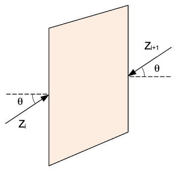
After solving for \(Q\), we note that \(Q_i\) can be expressed in terms of the interslice forces \(Z_i\) and \(Z_{i+1}\) as follows:
\(Q_i = Z_i - Z_{i+1} \qquad (66)\)
Starting from the left side, we can calculate the interslice forces iteratively. For the first slice, we set \(Z_1 = 0\). For each subsequent slice, we calculate the interslice forces as:
\(Z_{i+1} = Z_i - Q_i \qquad (67)\)
Line of Thrust
The line of thrust is the line along which the side forces \(Z\) act on the slice. It is calculated by starting from the left side and summing moments about the center of the base of the slice. The moments are calculated as follows:
\(M_o - Z_i \sin \theta \dfrac{\Delta x}{2} - Z_{i+1} \sin \theta \dfrac{\Delta x}{2} - Z_i \cos \theta (y_{t,i} - y_b) + Z_{i+1} \cos \theta (y_{t,i+1} - y_b) = 0 \qquad (68)\)
where \(y_{t,i}\) and \(y_{t,i+1}\) are y coordinates of the line of thrust of the left and right side, respectively. If \(y_{t,i}\) is known, we can solve for \(y_{t,i+1}\) as follows:
\(y_{t,i+1} = y_b - \left[ \dfrac{M_o - Z_i \sin \theta \dfrac{\Delta x}{2} - Z_{i+1} \sin \theta \dfrac{\Delta x} {2} - Z_i \cos \theta (y_{t,i} - y_b)}{Z_{i+1} \cos \theta} \right] \qquad (69)\)
For the first slice, we can set \(y_{t,1} = y_{lb}\) where \(y_{lb}\) is the lower left corner of the slice. For each subsequent slice, \(y_{t,i}\) is equal to \(y_{t,i+1}\) from the previous slice. We can use that in equation (69) to calculate \(y_{t,i+1}\). We repeat this process for all slices until we reach the right side of the slope.
Interpreting the Admissibility Warnings
Spencer's method (and Morgenstern–Price, which shares this machinery) returns a list of
admissibility notes in results['warnings'] when the accepted solution carries base
tension on a cohesionless slice, significant interslice tension, or a line of thrust
that leaves the slices. The warnings never change the factor of safety — they describe
the internal force distribution — and they are not all equally alarming.
A thrust line running outside the slices near the crest is common and natural wherever the top of the slope is cohesive: that soil is in tension, the interslice forces reflect it, and the reconstructed thrust line responds by leaving the physical slice. The classical remedy is a tension crack, which removes the tension zone from the analysis — but a crack should be modeled only when the reference analysis or the field condition calls for one; adding a crack merely to tidy the thrust line changes the problem being solved. A deep-seated case like the Talbingo dam (VP5) shows exactly this signature while its factor of safety matches the moment methods and the published values.
By contrast, large interslice tension transmitting a concentrated force, or base tension on a cohesionless slice, are signs the constant-\(\theta\) solution itself is strained — see the VP30 discussion in the verification corpus for a worked case where the warnings flag a root that is arithmetic rather than mechanics.