Sample Problems - Seepage Analysis
Verification benchmarks (the analytical anchors and the SEEP2D cross-check) are documented on the seepage verification page.
The following examples illustrate how to use XSLOPE to perform seepage analysis. The problems feature both saturated and unsaturated conditions. Each of the Excel input files below can be used with the following notebook which has been set up specifically for running seepage analyses:

These problems feature standalone seepage analyses. For instructions on how to run an integrated seepage analysis with slope stability analysis, see the Integrated Seepage and Slope Stability Analysis page.
1. Sheetpile with Clay Blanket
This is a saturated problem with a partially penetrating sheetpile and a clay blanket. It should have an upstream head BC = 13m up to the tip of the blanket and a downstream head BC = 10m. The profile line should follow the edge of the sheetpile (down and then back up) with a small gap to ensure that there is a crack in the resulting mesh.
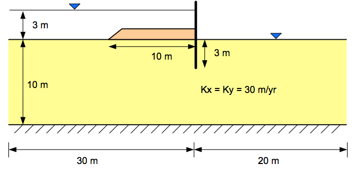
The following Excel file illustrates how the inputs should be structured. Since this is a fully saturated problem, the kr0 and h0 material parameters are ignored.
Excel input file: xslope_clay_blanket.xlsx
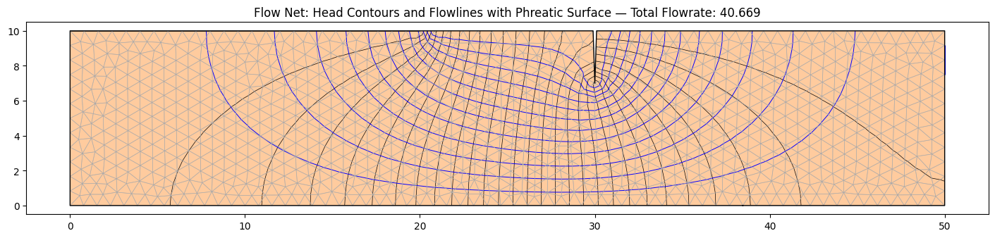
The solution should look something like this:
2. Sea Trench
This is another saturated problem representing the excavation of a trench in a harbor supported by a parallel set of sheetpile walls. The sheetpiles pass through an upper silt layer down to a lower permeability silty clay layer.
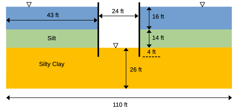
The properties of the soil layers are as follows:
| Soil Layer | K1 | K2 |
|---|---|---|
| Silt | 0.5 | 0.5 |
| Silty Clay | 0.1 | 0.1 |
Since this is a fully saturated problem, the kr0 and h0 material parameters are ignored. The problem set up requires 3 profile lines: 1 at the top of the silt layer on the left side, 1 at the top of the silt layer on the right, and 1 at the top of the silty clay layer that goes all the way from the left side to the right side of the problem. This profile line includes a small gap at the location of each sheetpile penetration to create a no-flow boundary along the edge of the sheetpile. The following Excel file illustrates how the inputs should be structured.
Excel input file: xslope_sea_trench.xlsx
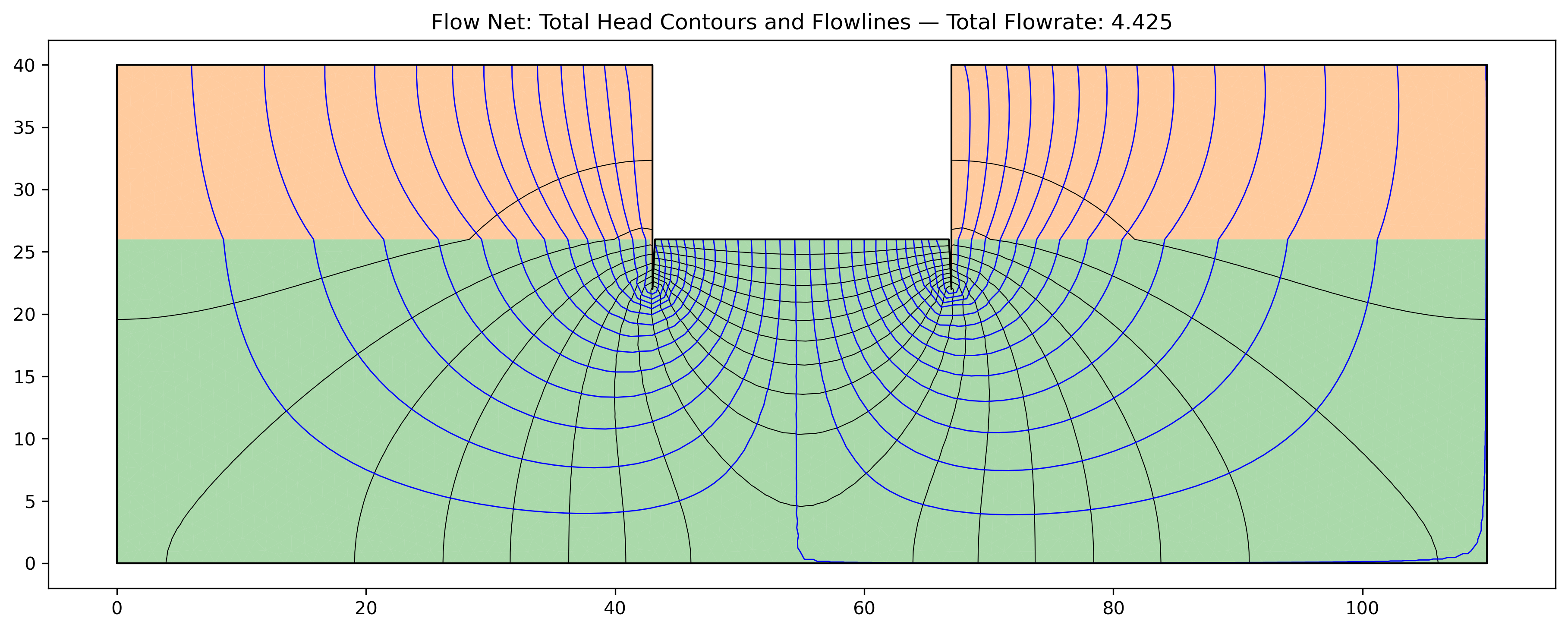
Solution:
3. Earth Dam with Core
The following diagram illustrates a simple earth dam with a clay core and a granular shell:
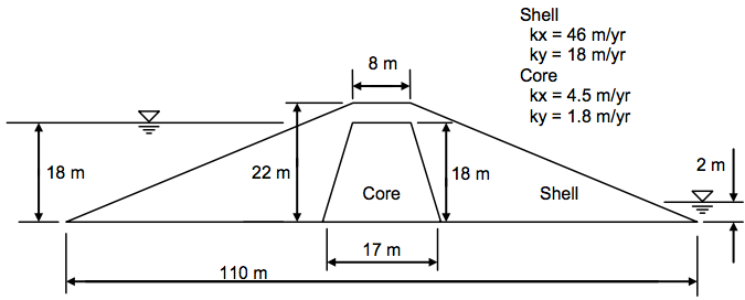
This problem requires an upstream head BC, a small downstream head BC, and a downstream exit face BC from the crest of the dam down to the tailwater. The conductivities used in the input file are: shell k1 = 56, k2 = 18; core k1 = 4.5, k2 = 1.8 (ft/yr — the sketch's "46 m/yr" shell label is superseded by these values). To build the input file, the following list of coordinates can be used:
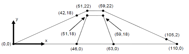
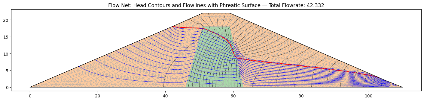
In this case, the solution is partially saturated, so the kr0 and h0 parameters must be specified for each material. The following Excel file contains a complete set of inputs for this problem:
The solution should look something like this:
4. Earth Dam with Core — van Genuchten Unsaturated Model
This is the same earth dam as Problem 3 — identical geometry, conductivities, and boundary conditions — but the unsaturated zone is modeled with the van Genuchten relative-conductivity function (unsat = "vg") rather than the linear front. Only the per-material unsaturated parameters change: the a column (van Genuchten α) and the n column, set to representative values for the shell (sandy loam) and core (loam), converted to the model's length unit (1/ft). See the van Genuchten Model section for the typical-value table and the unit convention for α.
The solution should look something like this:
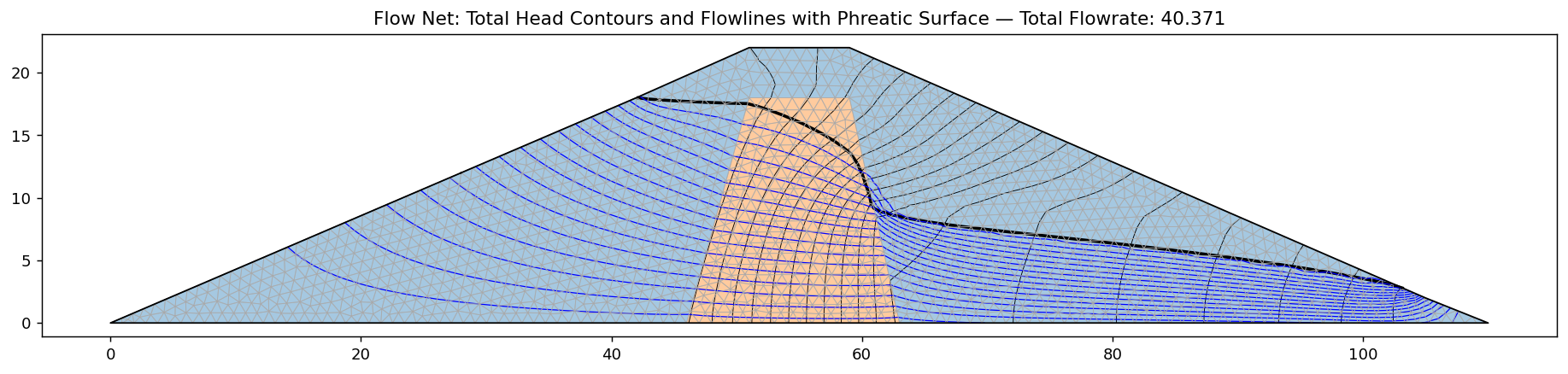
The computed flow rate (≈40.4) is close to the linear-front result of Problem 3 (≈42.4): with both models calibrated to the same soils, the unsaturated conductivity curve has little influence on the through-flow — consistent with the modeling guidance in the seepage overview.
5. Johnson Reservoir
This is another earth dam problem with a shell, a core, and a foundation.
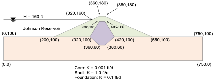
In this case, there is an upstream head BC = 160 ft and a downstream head BC = 100 ft on the flat part of the downstream foundation. The entire back side of the dam is an exit face BC. Again, this is a partially saturated problem.
The following file illustrates how to prepare the inputs:
The solution should look something like this:
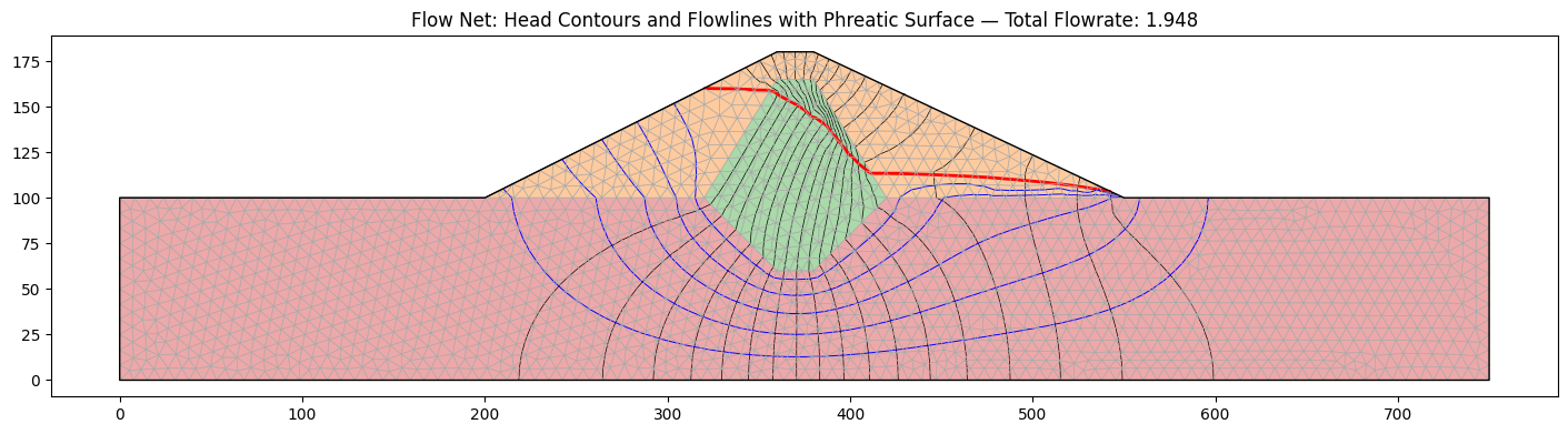
Verification — SEEP2D cross-check. This problem doubles as a verification
benchmark against an established code: it was exported to a SEEP2D input file
with the exact same tri3 mesh topology, boundary conditions, and material
parameters (benchmarks/run_seep2d_compare.py) and solved with the original
USACE/WES SEEP2D Fortran program (Tracy, USACE Waterways Experiment Station).
Identical-mesh comparison over all 2,604 nodes:
| Quantity | XSLOPE | SEEP2D | Diff |
|---|---|---|---|
| Total discharge q (ft³/day per ft) | 1.9575 | 1.9603 | -0.14% |
| Nodal heads | RMS Δh = 0.105 ft | (60-ft head range) | 0.18% |
The largest local head difference (~2 ft) occurs adjacent to the free surface, where the two codes' unsaturated relative-permeability treatments differ in detail; the bulk flow field agrees to about 0.1 ft. See the Verification page.
6. Earth Dam with Core and Filter
This problem has the following cross-section:
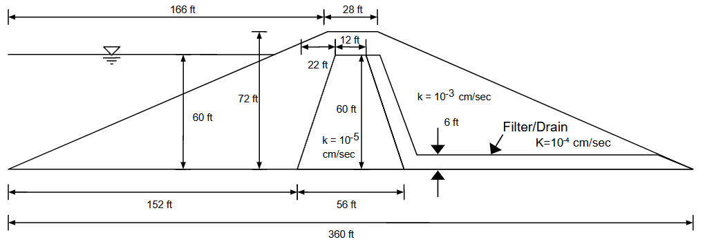
In this case, there is a single upstream head BC = 60ft and the entire backside of the dam is an exit face BC.
The following Excel file contains the problem inputs:
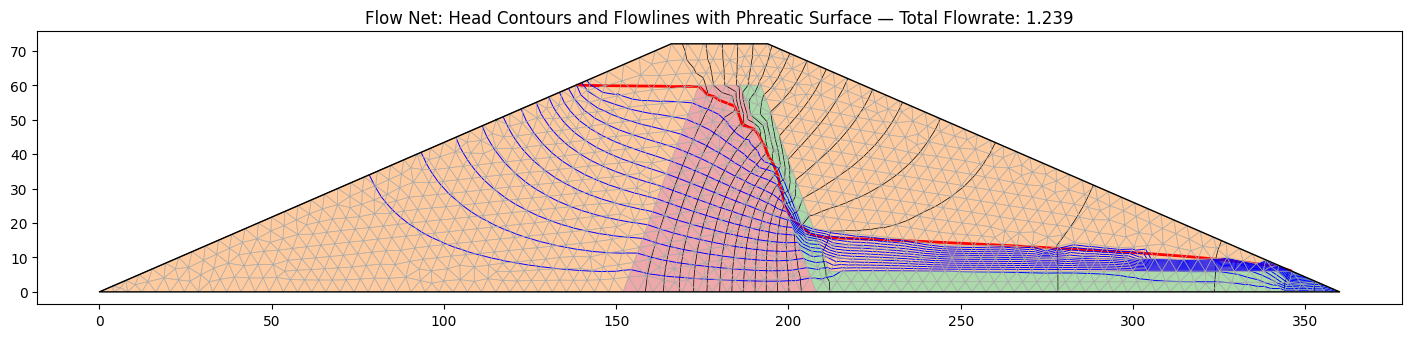
The solution should look something like this:
7. Levee with Grouted Foundation
The following problem represents a levee underlain by a foundation with a grout curtain.
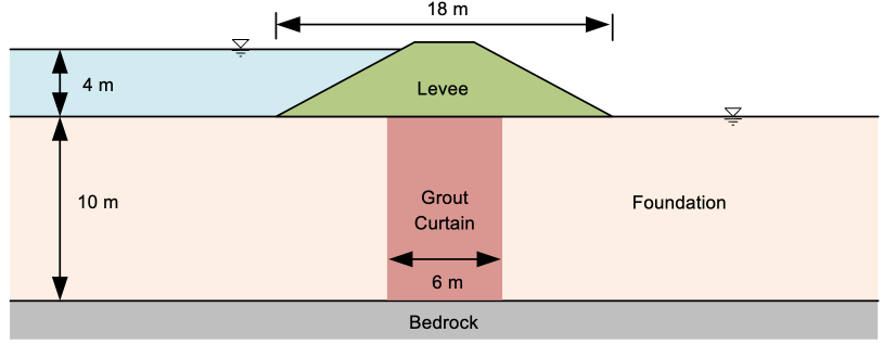
The material properties of the soil layers are as follows:
| Soil Layer | K1 [m/day] | K2 [m/day] | \(\alpha\) | kr0 | h0 |
|---|---|---|---|---|---|
| Levee | 0.5 | 0.2 | 0 | 0.001 | -1 |
| Grout Curtain | 0.2 | 0.2 | 0 | 0.001 | -1 |
| Foundation | 2 | 1 | 0 | 0.001 | -1 |
The coordinate geometry is shown here (the foundation spans elevations 0 to 10, and the grout curtain extends the full foundation depth — the coordinates labeled along the bottom edge are at elevation 0):
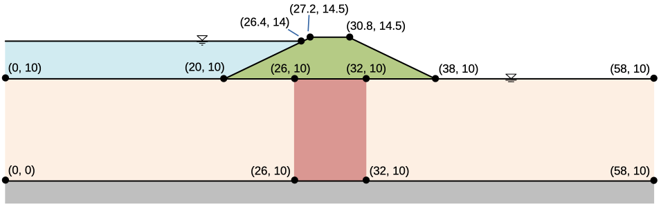
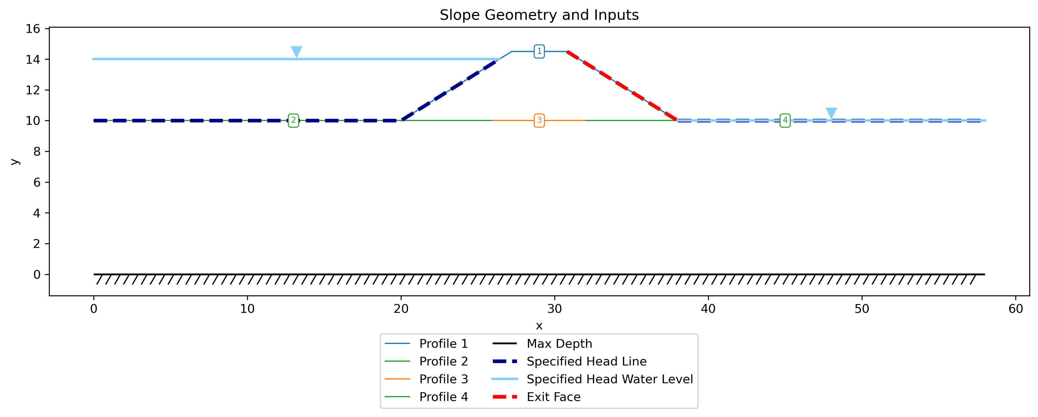
The following file illustrates how to prepare the inputs. Unlike the other
samples, this one defines the geometry with the polygon sheet — each
material zone (levee, grout curtain, foundation) is entered as a closed polygon
rather than as profile lines:
Inputs plotted with the XSLOPE plot_inputs() function:
Note
The finite-element mesh is shown overlaid on the material zones above because
this model has already been run — the mesh is generated during the seepage
solve and stored with the model. plot_inputs() draws the mesh whenever one is
present; for a model that has not yet been meshed, only the polygon geometry is
shown.
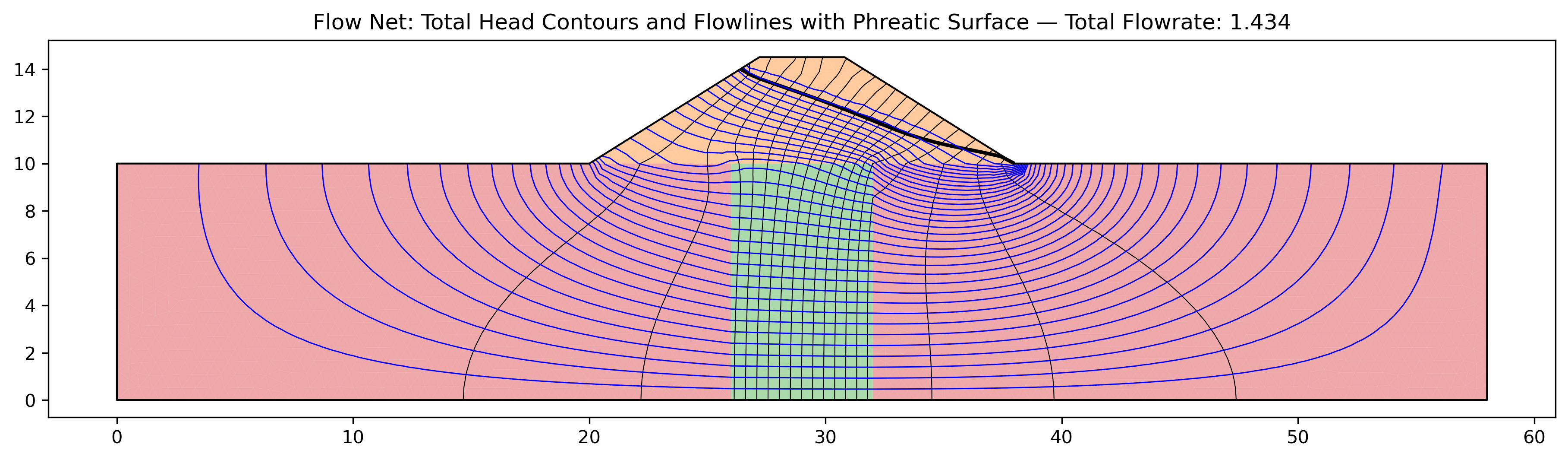
Solution:
The remaining problems are verification benchmarks: analytically-anchored cases used to validate the seepage implementation. Each is locked into the automated regression suite. See also the Verification page.