Editing Inputs
Studio is, at heart, a structured editor over the model's inputs. Every edit you make updates the in-memory model and re-renders the canvas immediately. This page covers the editors, double-click-to-edit, undo/redo, styles, and the file lifecycle.
The Inputs tree and the editors
The Inputs tree (left dock) lists every input category. Click a category to open its editor:
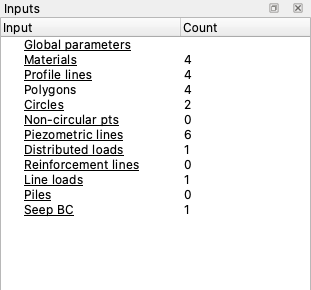
| Category | What you edit |
|---|---|
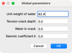
| Global parameters | Unit weight of water, tension-crack depth/water, seismic coefficient, max depth. |
| Materials | The material table — name, unit weight, strength option and parameters, and (by mode) hydraulic and elastic properties. |
| Profile lines | The profile-line geometry (master/detail); rebuilds the ground surface and material zones. |
| Polygons | Material-zone polygons (for polygon-based models). |
| Piezometric lines | The two piezometric lines. |
| Failure surfaces | Circles (center, radius/depth/intercept) or the non-circular surface (vertex table). |
| Distributed loads | The two distributed-load sets. |
| Reinforcement | Reinforcement lines (rebuilt into the engine's display format). |
| Line loads | Concentrated line loads (force per unit width) on the ground surface. |
| Piles | Pile lines. |
| Seepage BC | Specified-head lines, specified-flux lines, and exit faces (two BC sets). |
Editors are forms (for scalars) or tables (for tabular data). Tabular editors let you add, remove, and reorder rows.
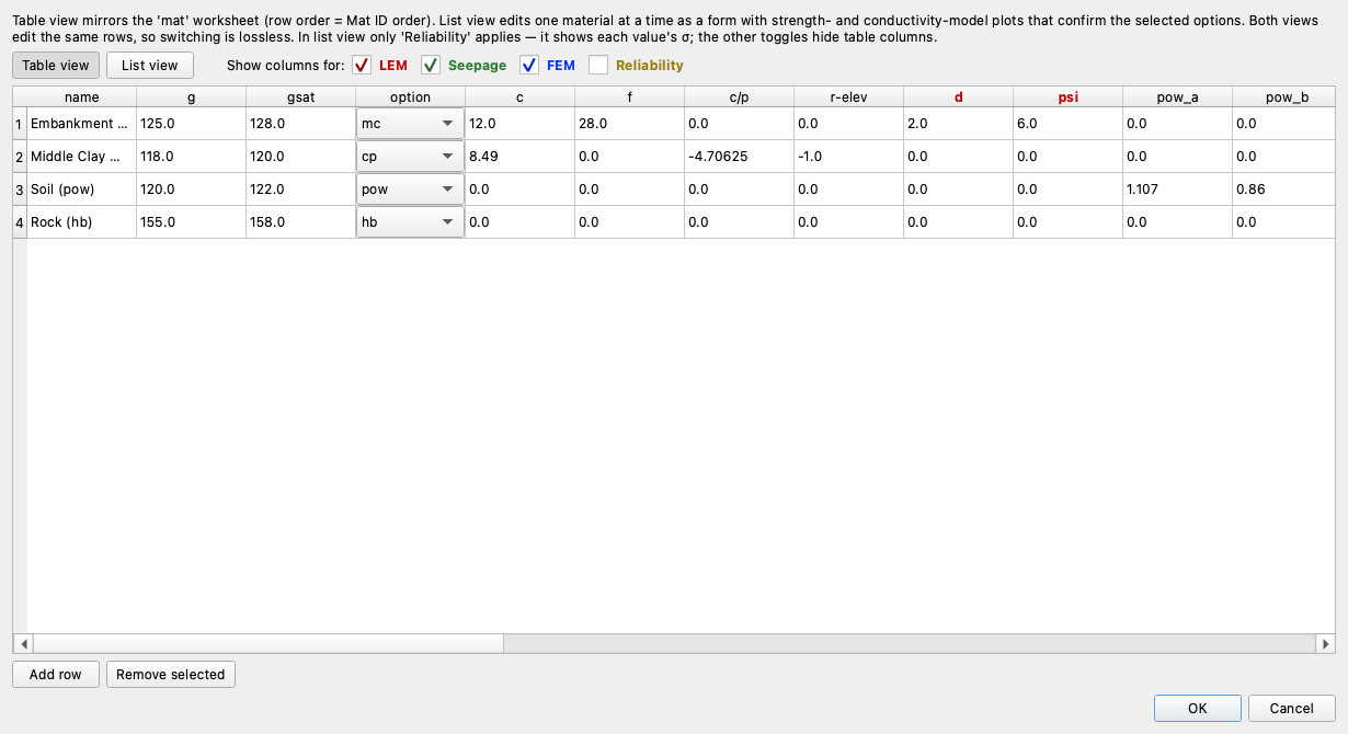
The materials editor has two interchangeable views. Table view mirrors the
mat worksheet row-for-row, with Show columns for toggles (LEM / Seepage /
FEM / Reliability) that hide the columns an analysis doesn't use:
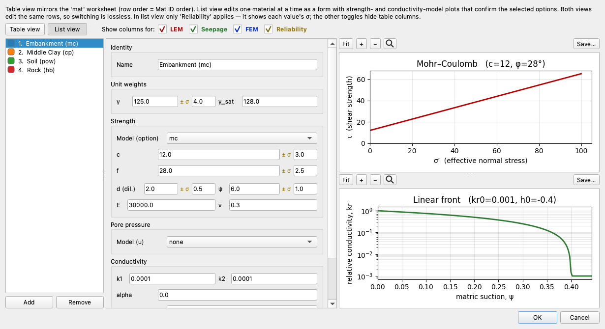
List view edits one material at a time as a grouped form — Identity, Unit weights, Strength, Pore pressure, Conductivity — showing only the fields the selected strength and conductivity options use. Turning on the Reliability toggle here reveals the ± σ field next to each value instead of hiding columns. Two confirmation plots on the right — the strength envelope and the unsaturated-conductivity curve — redraw as you type, so a wrong option choice is obvious at a glance:
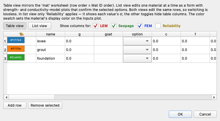
The Display color swatch under Identity sets the material's color on the plots (Reset returns it to the default palette); the same swatch is the first column of the table view. Both views edit the same rows, so switching is lossless.
Edits are validated, applied to the model, mark the document dirty (an asterisk in the title bar), and re-render the affected layers. Records preserve fields that aren't shown in a given editor, so editing one column never drops the others.
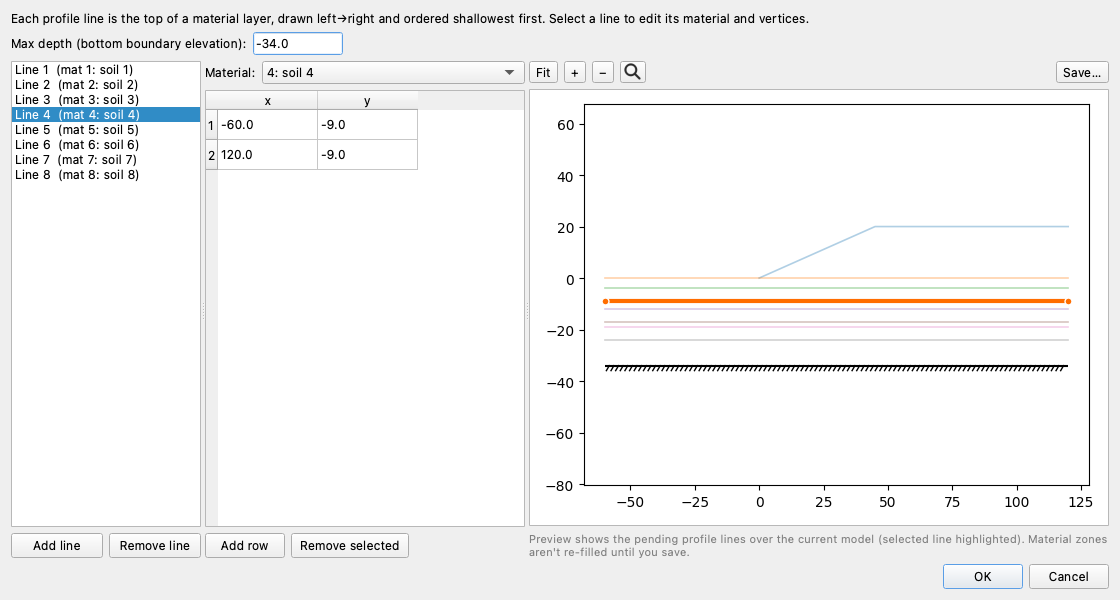
The geometry editors (profile lines and polygons) use a master/detail layout — pick a line on the left, edit its vertices on the right. A live preview pane redraws the section as you type, with the selected line highlighted, so a mistyped vertex is visible before you commit:
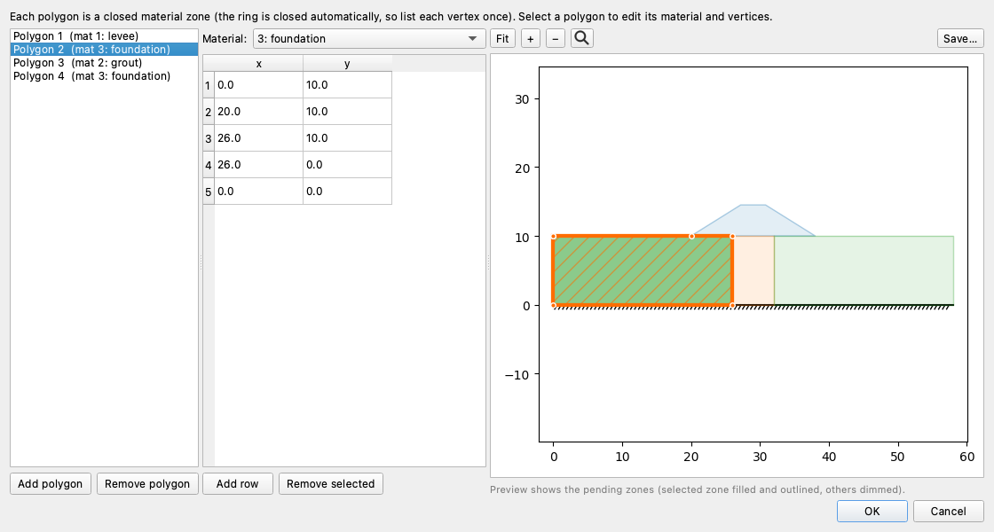
The polygons editor is the same dialog for polygon-based models — the preview fills the selected zone and dims the rest:
Profile-based vs. polygon-based models
A model defines its geometry either through profile lines (stacked surfaces, with zones derived from them) or directly as polygons. The Inputs tree marks Polygons editable only when there are no profile lines; otherwise edit the Profile lines. Both use the same master/detail geometry dialog.
The remaining feature editors follow the same pattern — a table (or master/detail list) plus a live preview of the feature on the section.
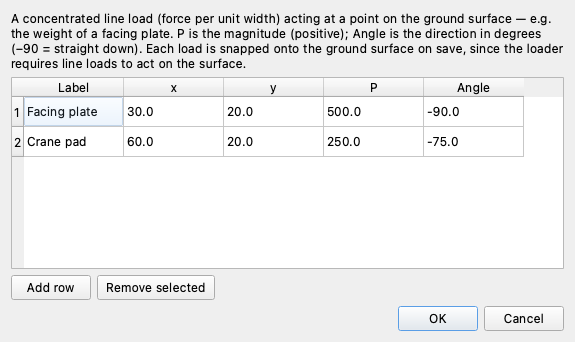
Line loads are concentrated forces per unit width acting at a point on the ground surface (a facing plate, a crane pad). Each row is a point, a magnitude P, and an Angle (−90° = straight down); loads are snapped onto the ground surface on save:
Like the materials editor, the reinforcement and pile editors each offer two interchangeable views. The default List view edits one line at a time as a grouped form beside the live section preview; Table view is available for bulk entry of many lines. Both views edit the same rows, so switching is lossless, and the Show columns for (LEM / FEM) toggles hide the columns an analysis doesn't use in the table.
Reinforcement lines are grouped as Geometry (endpoints), Capacity (Tmax, Tres, E, Area), Anchorage (Lp1/Lp2 pullout lengths, Tend1/Tend2 end capacities, Spacing), and Type — picking a Type (geosynthetic, nail, tieback, anchor) defaults Dir and Appl, and a blank Type means a generic tensile line. The preview draws the lines on the section with the selected one emphasized and its pullout breakpoints marked:
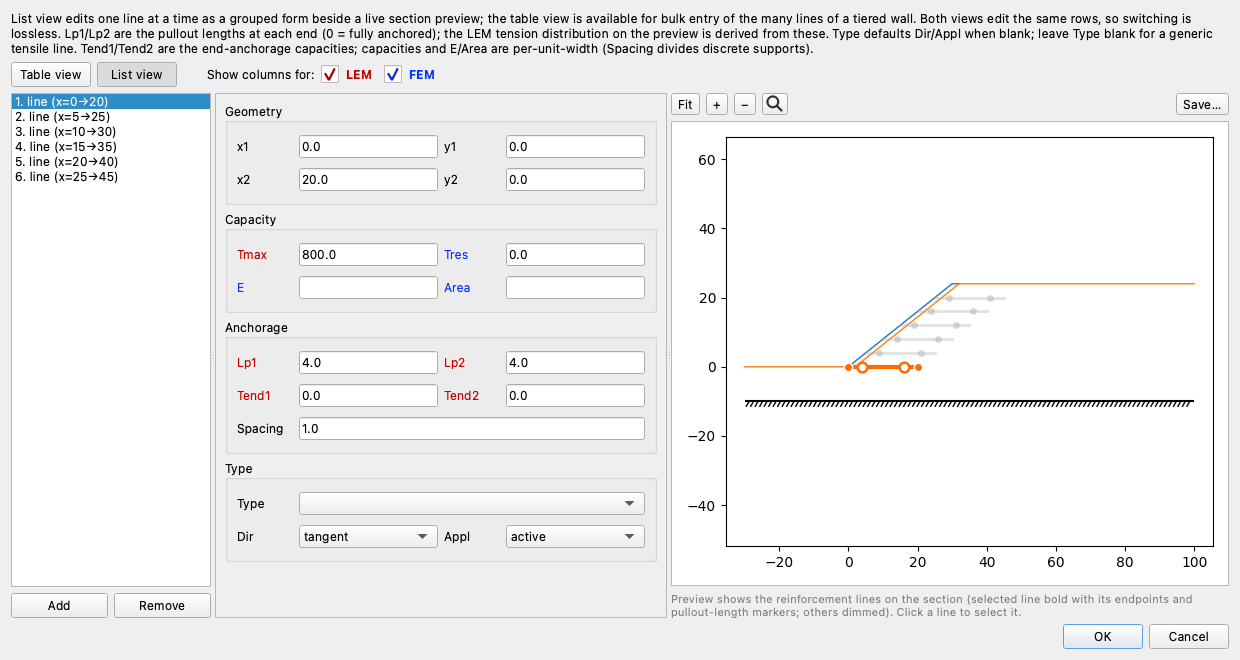
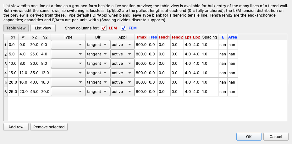
Table view lays every column out at once — the bulk-entry path for the fifteen-plus lines of a tiered wall:
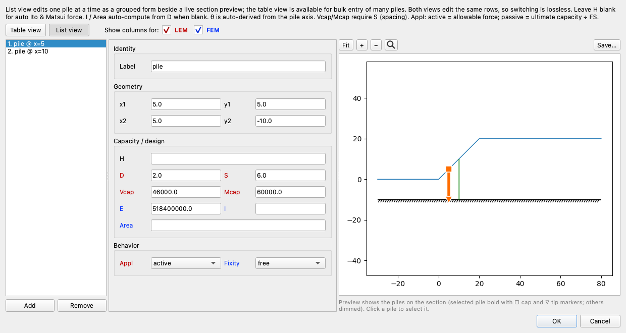
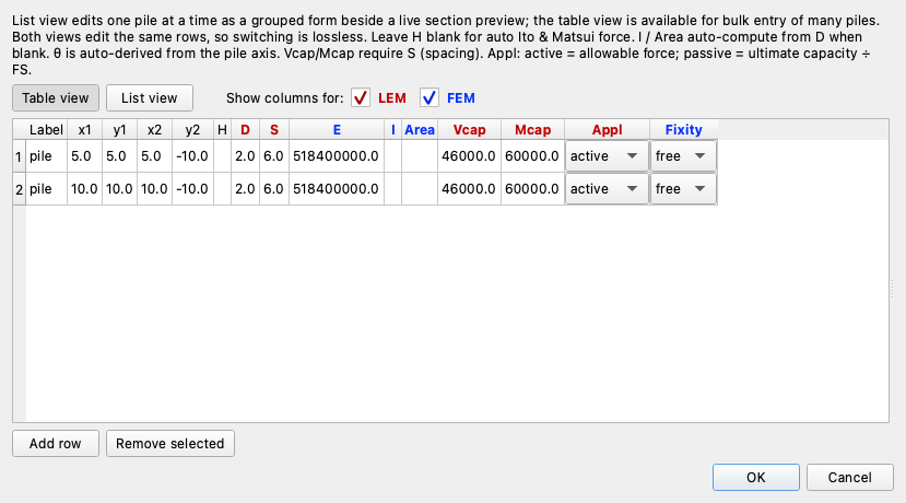
Piles group their fields as Geometry, Capacity / design (H, D, S, Vcap, Mcap, and the FEM E/I/Area), and Behavior — the Appl dropdown chooses how the pile resistance enters the analysis (active = allowable force; passive = ultimate capacity ÷ FS), and leaving H blank auto-computes the Ito & Matsui force. A model rarely has more than a few piles, so the list view is usually all you need; the table is there for the exceptions:
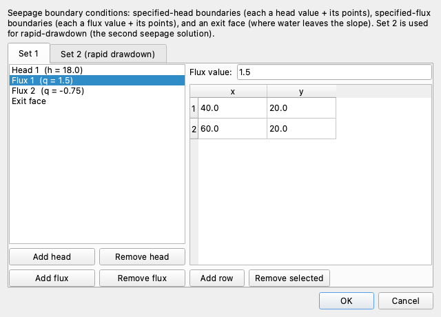
Seep BC is a master/detail editor over the two BC sets (Set 2 drives rapid drawdown): specified-head lines (a head value plus its points), specified-flux lines (Add flux, a Flux value plus its points), and the exit face:
Double-click to edit
On the Inputs view, double-clicking a feature on the canvas opens the right editor with the picked item pre-selected — no need to find it in the tree first.
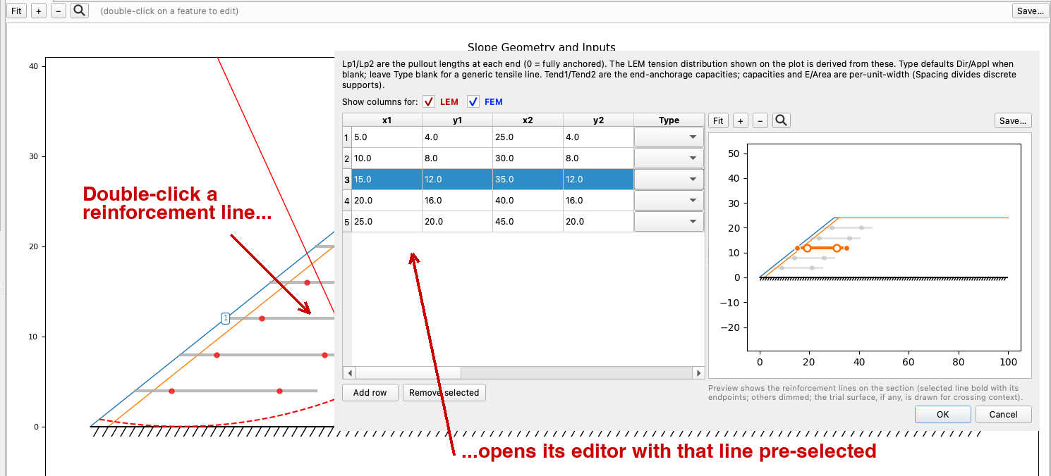
Studio maps the click to the drawing's coordinates and hit-tests the geometry, so this works on:
- profile and polygon lines (opens the geometry editor at that line),
- the max-depth line, piezometric lines, distributed loads, line loads, reinforcement, piles,
- failure circles and non-circular points,
- seepage boundary conditions (specified-head lines, specified-flux lines, and exit faces),
- a material-zone interior (falls back to the materials editor).
The hit-test is mode-aware — seepage BCs are only pickable in Seepage mode, distributed loads only outside it — matching what the plot draws. Result views are view-only; double-click-to-edit is the Inputs view only.
Undo and redo
Every edit — whether from an editor, a canvas pick, or the AI assistant — is captured on a snapshot undo stack. Undo and redo are on the toolbar (and the Edit menu, with the usual Ctrl/Cmd+Z and Shift+Ctrl/Cmd+Z shortcuts).
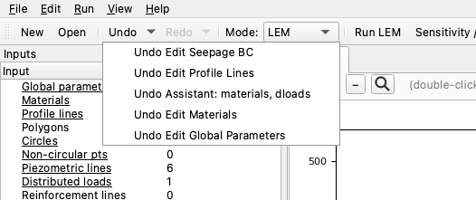
Each toolbar button is a split-button: clicking it undoes or redoes one step, while the dropdown arrow shows the labeled history — "Edit Materials", "Edit Profile Lines", "Assistant: materials, dloads" — and selecting an entry jumps straight to that point in one action (an Office/Photoshop-style history).
A few behaviors worth knowing:
- Assistant edits are undoable just like manual ones — if the assistant changes something you didn't want, undo reverts it. A failed assistant snippet rolls back automatically and leaves nothing on the stack.
- Undoing or redoing back to the last-saved state clears the dirty flag (the title asterisk disappears).
- The history is capped (the most recent 100 steps are kept).
Stale results and the mesh
Results are derived from the inputs, so editing an input that a result depended on makes that result stale. Studio handles this automatically:
- Editing any input clears a stale LEM solution (its tab is removed).
- Editing the geometry (profile/polygon lines, max depth, reinforcement, piles) also clears the mesh, so Seepage and FEM re-gate on a fresh Build Mesh.
- Undo/redo apply the same rule — stale solution tabs are dropped, and the mesh follows the restored geometry.
This is why an edit visibly refreshes the Inputs view: Studio always leaves you on a valid picture.
Styles
Styles are the persistent, project-global visual identity of each feature — material fill color/hatch/opacity, and line color/style/width for features like piezo lines, circles, and reinforcement. Open the Styles… button at the bottom of the Display dock to edit them, with a live preview.
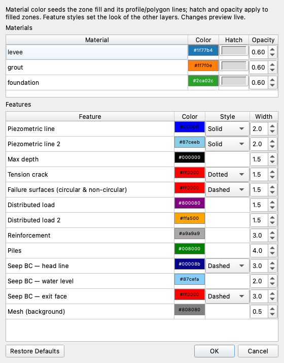
- Materials are styled by their
mat_id: a fill color from an earth-tone palette, a soil-ish hatch, and an opacity. - Features carry a color, line style (where conventional), and width.
- Restore Defaults clears all customizations in one click.
Styles are saved per project in a {stem}_styles.json sidecar next to the Excel
file, holding only the differences from the built-in defaults. A project with no
customizations writes no sidecar, and opening a project loads its styles
automatically.
Styles vs. Display options
Styles are how a feature looks and persist with the project. The Display options in the dock are what a plot shows — per-view and not saved. Visibility toggles (show/hide a feature) are a display concern and live with the display options, not the styles.
File lifecycle
Studio reads and writes the same Excel format as the xslope library, so files
round-trip between Studio, scripts, and notebooks.
| Action | What happens |
|---|---|
| New | Creates an empty project — every category present but blank, a blank canvas. Build it up with the editors (start with a material and a profile line) or the assistant, then Save As. |
| Open | Loads an Excel file and renders the Inputs view. Auto-loads any {stem}_mesh.json, {stem}_seep.csv, FEM, and {stem}_styles.json sidecars, restoring saved seep/FEM solutions without re-solving. |
| Save | Writes back to the same file, preserving the template formatting, and reconciles the mesh/seep/FEM/style sidecars against the current model. |
| Save As | Writes a new file through the bundled blank template. |
Studio keeps a Recent files list, and prompts to save unsaved changes before New, Open, or closing.
Importing geometry from CAD
A model can also be started from a DXF drawing via File → Import DXF… — a wizard maps each CAD layer to an input feature. See Importing and exporting DXF.